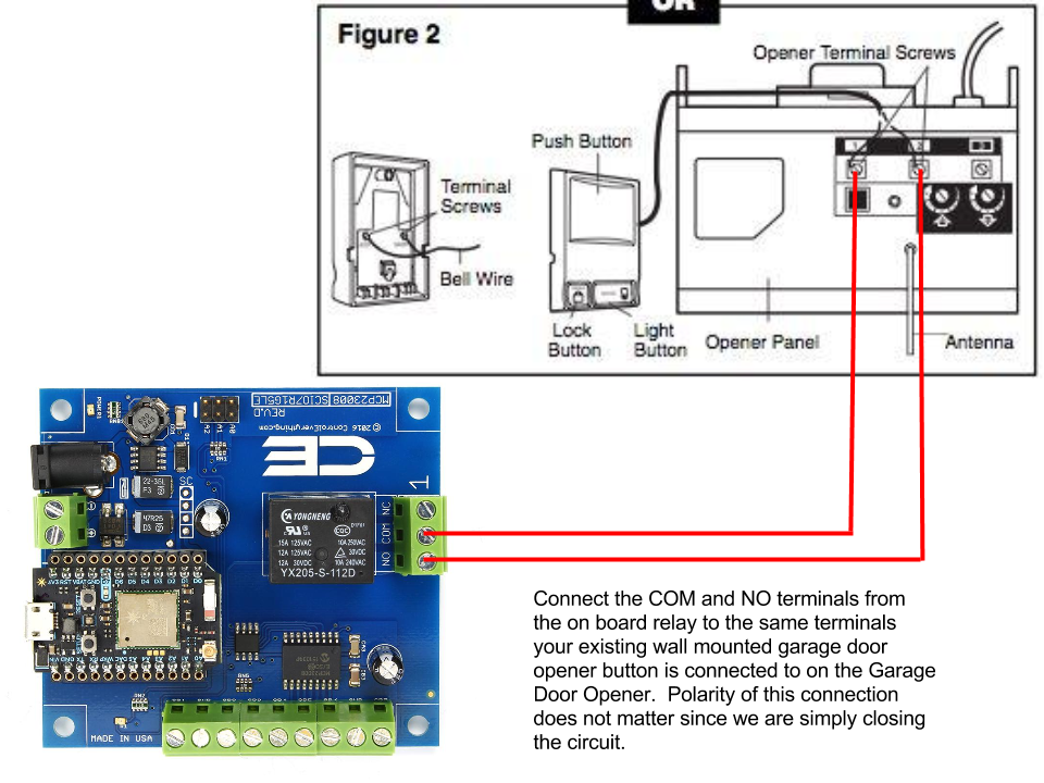
Using the other end of the jumper wire, connect the wall button to the back of the opener. Kit includes 1 wall plate, 22 of tubing, and one hardware packet.
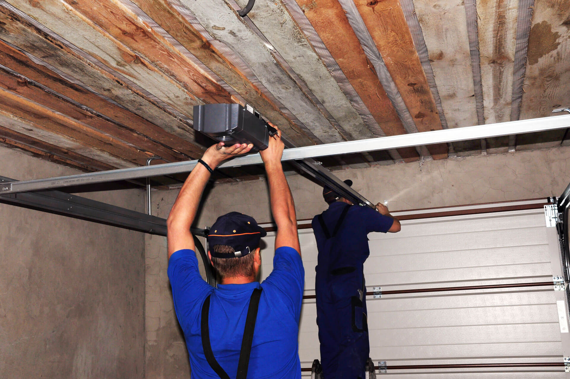
Garage Door Wire Voltage, This video will show you how to assemble and install a chamberlain garage door opener in a garage with a sectional. Use three kits per door.
 How Is This Wired? Garage Door Sensor Wire Question From diychatroom.com
Your garage door kit should have a coil of wire colored white/red stripe, and, if. Wire size (awg) current rating* insulation diameter (inches) 20 gauge 8.9 amps 0.060″ 18 gauge 11.4 amps 0.071″. How many volts is a garage door opener button? If the wire is building wire (e.
Garage door opener prewire and framing guide by bob moulton of moulton custom door company of duxbury, vt.
Wiring diagram for garage door opener. One run of wire from each side of the door to the opener. Garage door opener sensors wiring issues. Low voltage connections like that don�t need to be in a box. The voltage at the ‘door open’ switch is 8 vdc open, 0 vdc closed to case ground. There aren�t other nicks in the wire that i can find but neither of the garage door sensors light up.
 Source: schematicandwiringdiagram.blogspot.com
How many wires do you need for a garage door opener? This circuit should be on a protected gfci outlet all by itself from the electrical panel. How many volts is a garage door opener button? Junction boxes for low voltage wiring for the garage door accessories ideally will be in a plastic gang box with a coaxial cable cover.
 Source: untpikapps.com
Tuofeng 22awg electrical wire 100 ft 22 gauge led wire 2 pin extension cable wire red black wires 12v/24v dc cable for led strips single colour. There aren�t other nicks in the wire that i can find but neither of the garage door sensors light up. 4.7 out of 5 stars. Garage door opener wiring garage door openers use a.
 Source: hackster.io
This video will show you how to assemble and install a chamberlain garage door opener in a garage with a sectional. Garage door openers use a receptacle in the ceiling for power. How many wires do you need for a garage door opener? Romex) and(/or) it is in a wall box, it almost certainly is 120 v ac. This voltage.
 Source: untpikapps.com
Diagram overhead door wiring full version hd quality. The wired controller and sensors use low voltage wiring (usually 24v) to connect to the motor unit. If you check the garage door, you will find that both sides of the garage door have. 4.7 out of 5 stars. The first rule of bypassing garage door sensors is not related to sensors.
") Source: garagedoorzone.forumotion.net
Source: garagedoorzone.forumotion.net
This circuit should be on a protected gfci outlet all by itself from the electrical panel. Romex) and(/or) it is in a wall box, it almost certainly is 120 v ac. Wiring diagram for garage door opener. Now that you know a little bit more about garage door sensors, you should be able to choose the right sensor for your.
 Source: blog.adafruit.com
In my quest to fix some of the annoying things around the house, today i�m working on my garage door opener setup. How many volts is a garage door opener button? Now that you know a little bit more about garage door sensors, you should be able to choose the right sensor for your installation and ensure that it’s properly.
 Source: diynot.com
For some reason my garage door sensor wire was loose and got caught in the track as the door was opening. You can pick it up at any hardware store. There aren�t other nicks in the wire that i can find but neither of the garage door sensors light up. Signs that represent the parts. Junction boxes for low voltage.
 Source: diychatroom.com
Check the connections at each sensor and at the door opener. If the garage door is still not working, then maybe you have a bad circuit board. A garage door opener requires a simple 15 or 20 amp 120 volt circuit. One run of wire from each side of the door to the opener. Blue wire nuts work good or.
 Source: triocleonice.com
This voltage is used for the safety sensors and controls. The ac 1/2hp dc garage door opener, wiring diagram for harnesses have a high voltage and low voltage wire harnesses that connect to different components in the operator, below is a description of which wires connect to which components. Both these circuits need a minimum of two wires but four.
 Source: community.smartthings.com
Garage door opener wiring garage door openers use a receptacle in the ceiling for power. Diagram overhead door wiring full version hd quality. Tuofeng 22awg electrical wire 100 ft 22 gauge led wire 2 pin extension cable wire red black wires 12v/24v dc cable for led strips single colour. How do you intend to adjust your voltage at home so.
 Source: objectpartners.com
For a yellow learn opener, if the wall control led lit up. Use three kits per door. The wired controller and sensors use low voltage wiring (usually 24v) to connect to the motor unit. Diagram overhead door wiring full version hd quality. The circuit must be grounded.
 Source: wholefoodsonabudget.com
Signs that represent the parts. I always use a s/g plaster ring and trim with a plate. The 24v is made by a small transformer within the control box. What is the proper voltage for a garage door sensor? The voltage at the ‘door open’ switch is 8 vdc open, 0 vdc closed to case ground.
 Source: triocleonice.com
Guess the wiring that came with the opener was. Both these circuits need a minimum of two wires but four wire is better, 22 gauge or better with a tracer for polarity identification. One run of wire from each side of the door to the opener. Signs that represent the parts. For some reason my garage door sensor wire was.
 Source: bosco-mylove.blogspot.com
How many wires do you need for a garage door opener? Using the other end of the jumper wire, connect the wall button to the back of the opener. How many volts is a garage door opener button? While the replacement button burned very brightly for a few days, apparantly this did not cause the door mechanism to operate. Raise.
 Source: pinterest.com
Typically 22/2 bell wire is used. A few inches of wire got shredded and the garage door stopped because it lost the sensor. 4.7 out of 5 stars. If extra tubing is ordered, the stock 22 inches of tubing will be added to the length of bulk tubing ordered. Leave a minimum of 3 ft.
 Source: 365garagedoorparts.net
Your garage door kit should have a coil of wire colored white/red stripe, and, if. Of extra wiring at the photo eye junction boxes and 3‘ to 4’ ft. This circuit should be on a protected gfci outlet all by itself from the electrical panel. Garage door sensors use low voltage, which is why they’re safe to use in residential.
 Source: trstn.com
There aren�t other nicks in the wire that i can find but neither of the garage door sensors light up. The wired controller and sensors use low voltage wiring (usually 24v) to connect to the motor unit. A few inches of wire got shredded and the garage door stopped because it lost the sensor. Wiring diagram for garage door opener..
 Source: worldvisionsummerfest.com
Now that you know a little bit more about garage door sensors, you should be able to choose the right sensor for your installation and ensure that it’s properly installed. Each part ought to be placed and connected with different parts in specific way. This video will show you how to assemble and install a chamberlain garage door opener in.
 Source: facybulka.me
Of extra low voltage wiring near the There aren�t other nicks in the wire that i can find but neither of the garage door sensors light up. One run of wire from each side of the door to the opener. Junction boxes for low voltage wiring for the garage door accessories ideally will be in a plastic gang box with.
 Source: schematicandwiringdiagram.blogspot.com
This voltage is used for the safety sensors and controls. If the wire is building wire (e. The first rule of bypassing garage door sensors is not related to sensors. You can pick it up at any hardware store. Using the other end of the jumper wire, connect the wall button to the back of the opener.
 Source: savjee.be
What is the proper voltage for a garage door sensor? Replace the damaged wires using new low voltage wires. If the wire is building wire (e. The circuit must be grounded. It�s only about 2 feet over my head, and i�m 5�4.
 Source: impressiveinteriordesign.com
The wired controller and sensors use low voltage wiring (usually 24v) to connect to the motor unit. Garage door opener wiring garage door openers use a receptacle in the ceiling for power. 4.7 out of 5 stars. Chamberlain garage door opener sensor wiring diagram sample. Junction boxes for low voltage wiring for the garage door accessories ideally will be in.
 Source: voteno123.com
Low voltage connections like that don�t need to be in a box. Romex) and(/or) it is in a wall box, it almost certainly is 120 v ac. Garage door sensors use low voltage, which is why they’re safe to use in residential applications. Diagram overhead door wiring full version hd quality. The first rule of bypassing garage door sensors is.
 Source: 2020cadillac.com
Those wires are colored white, and white with black stripe. If the garage door is still not working, then maybe you have a bad circuit board. Wiring diagram for garage door opener. Your garage door kit should have a coil of wire colored white/red stripe, and, if. Guess the wiring that came with the opener was.
 Source: triocleonice.com
This video will show you how to assemble and install a chamberlain garage door opener in a garage with a sectional. If the garage door is still not working, then maybe you have a bad circuit board. The motor and the control box are plugged into a 120v outlet. Those wires are colored white, and white with black stripe. There.