Many homeowners prefer switches to be installed on the home's interior, near access doors. • install door control within sight of garage door, out of reach of children at a minimum height of 5 feet (1.5 m), and away from all moving parts of door.
Garage Door Control Voltage, Using the other end of the jumper wire, connect the wall button to the back of the opener. If the garage door is still not working, then maybe you have a bad circuit board.
 Gocontrol Garage Door Controller / Chamberlain Liftmaster From reddit.com
When you tell the door to open or close you are not actually doing anything but energizing a contactor that�s located in the door opener. My mfi garage door opener ubiquiti community. It’s simpler to control what the motor is doing; In my quest to fix some of the annoying things around the house, today i�m working on my garage door opener setup.
It’s simpler to control what the motor is doing;
The low voltage (24v) bell wiring leading from the door control up to the opener is suspended I had thought about using this as a power supply, but was afraid is might. Measure voltage across wires that go to wall panel, then press and hold open/close button for at least 1 second. Any excess wire touching the circuit board could cause the door control to not work. The garage door opener chooses the necessary speed automatically. What happens when the lockout button is pushed, it closes the circuit but has a capacitor that changes the voltage as well as a holding the button closed for more than 2 seconds.
 Source: aliexpress.com
For a yellow learn opener, if the wall control led lit up. I had thought about using this as a power supply, but was afraid is might. When pressing the door control the voltage on the wire that went back up to the motor read 0.750 vac. What happens when the lockout button is pushed, it closes the circuit but.
 Source: community.hubitat.com
If the garage door is still not working, then maybe you have a bad circuit board. Jv yes it is low voltage wire and the system for the garage door is low voltage. This circuit should be on a protected gfci outlet all by itself from the electrical panel. These contactors/relays close and open sending 115/120 volts to the motor..
 Source: 365garagedoorparts.net
I figured that jumping the circuit would toggle the door, which it did. Garage door opener repair and troubleshoting. For safety reasons, below 1.9m of travel. These fundamental differences mean it’s much easier for your garage door operator to be battery backup capable, have soft start and stop, have better obstacle detection and quieter operation, said mattson. Any excess wire.
") Source: garagedoorzone.forumotion.net
Source: garagedoorzone.forumotion.net
The power in sending the signal to the garage door fully depends on the batteries’ voltage. My mfi garage door opener ubiquiti community. The voltage at the �door open� switch is 8 vdc open, 0 vdc closed to case ground. Simply attach two low voltage wired and run them back to the garage door openers two push button terminals. In.
 Source: all-electronics-online.com
What is the proper voltage for a garage door sensor? These fundamental differences mean it’s much easier for your garage door operator to be battery backup capable, have soft start and stop, have better obstacle detection and quieter operation, said mattson. This made me think that the door opening was a simple instance of closing the circuit for about half.
 Source: diyforums.net
There are also ties where there’s only a little power left in the battery which can weaken the amount of power it can give. Electric garage door opener stopped working no power green. Any excess wire touching the circuit board could cause the door control to not work. Garage door opener repair and troubleshoting. Raise the door to its highest.
 Source: swiftsly.com
It’s simpler to control what the motor is doing; I figured that jumping the circuit would toggle the door, which it did. If there are only two wires between the control panel and the garage door controller, then as others have said, some sort of multiplexing must be going on, either using some combination of diodes etc., voltage levels, dc.
 Source: removeandreplace.com
My relay shield was on gpio5, the dht shield was on gpio2, and i connected the reed switch on gpio13. These fundamental differences mean it’s much easier for your garage door operator to be battery backup capable, have soft start and stop, have better obstacle detection and quieter operation, said mattson. If voltage drops to 0v when button is pressed,.
 Source: insteon.com
Push up and down buttons simultaneously until the operator light blinks. For automatically closing the garage door, a tape switch is disposed on the garage floor in the. The wired controller and sensors use low voltage wiring (usually 24v) to connect to the motor unit. Users can easily measure the speed and force the motor is applying to the garage.
 Source: jenrathbun.com
A circuit for controlling an electrically operated garage door comprising a manually operated switch disposed within the garage. Garage door openers use a receptacle in the ceiling for power. Using the other end of the jumper wire, connect the wall button to the back of the opener. The garage door opener chooses the necessary speed automatically. Verify there is no.
 Source: diagramweb.net
Garage door opener repair and troubleshoting. I�m using a contactless voltage detector and it�s detecting voltage on both of those black and white wires, even though there is no garage door opener (let. Push up and down buttons simultaneously until the operator light blinks. Most all garage door openers are required to be plugged in and not hardwired. The garage.
 Source: dhowdy.blogspot.com
Remove the screw, then slide the door control up and off the wall. Using the other end of the jumper wire, connect the wall button to the back of the opener. For safety reasons, below 1.9m of travel. I had thought about using this as a power supply, but was afraid is might. Replace the damaged wires using new low.
 Source: walmart.com
There are also ties where there’s only a little power left in the battery which can weaken the amount of power it can give. This made me think that the door opening was a simple instance of closing the circuit for about half a second but made me unsure of what the true voltage was. My garage door opener has.
 Source: prontogaragedoor.com
The low voltage (24v) bell wiring leading from the door control up to the opener is suspended Jv yes it is low voltage wire and the system for the garage door is low voltage. My mfi garage door opener ubiquiti community. Push up and down buttons simultaneously until the operator light blinks. These contactors/relays close and open sending 115/120 volts.
 Source: hackster.io
What happens when the lockout button is pushed, it closes the circuit but has a capacitor that changes the voltage as well as a holding the button closed for more than 2 seconds. Verify there is no excess wire connected to the screw terminals on the back of the door control panel. For a yellow learn opener, if the wall.
 Source: reddit.com
Garage door openers include a photo electric sensor system to help prevent damage to the door or opener. The garage door opener chooses the necessary speed automatically. If there are only two wires between the control panel and the garage door controller, then as others have said, some sort of multiplexing must be going on, either using some combination of.
 Source: ebay.com.au
Garage door opener installers often locate door control switches in inconvenient locations. What is the proper voltage for a garage door sensor? For safety reasons, below 1.9m of travel. Garage door openers use a receptacle in the ceiling for power. Lift up the push button which activates the garage door.
 Source: next.gr
Push up and down buttons simultaneously until the operator light blinks. A circuit for controlling an electrically operated garage door comprising a manually operated switch disposed within the garage. The wired controller and sensors use low voltage wiring (usually 24v) to connect to the motor unit. It’s simpler to control what the motor is doing; • install door control within.
 Source: ebay.com.au
The power in sending the signal to the garage door fully depends on the batteries’ voltage. Move the door to the fully closed position. Electric garage door opener stopped working no power green. Users can easily measure the speed and force the motor is applying to the garage door; Simply attach two low voltage wired and run them back to.
 Source: aliexpress.com
I figured that jumping the circuit would toggle the door, which it did. Additional switch controls are available for single or multiple garage doors. In my quest to fix some of the annoying things around the house, today i�m working on my garage door opener setup. For all 2 wire garage door opener wall button systems. There is a brown.
 Source: hagensieker.com
Garage door openers use a receptacle in the ceiling for power. My relay shield was on gpio5, the dht shield was on gpio2, and i connected the reed switch on gpio13. 1 garage door opener mounting bracket. The voltage at the �door open� switch is 8 vdc open, 0 vdc closed to case ground. When pressing the door control the.
 Source: triocleonice.com
Garage door openers use a receptacle in the ceiling for power. It’s simpler to control what the motor is doing; To prevent possible serious injury or death from a closing garage door: The higher the voltage of the battery, the wider the range. Verify there is no excess wire connected to the screw terminals on the back of the door.
 Source: hometechtime.com
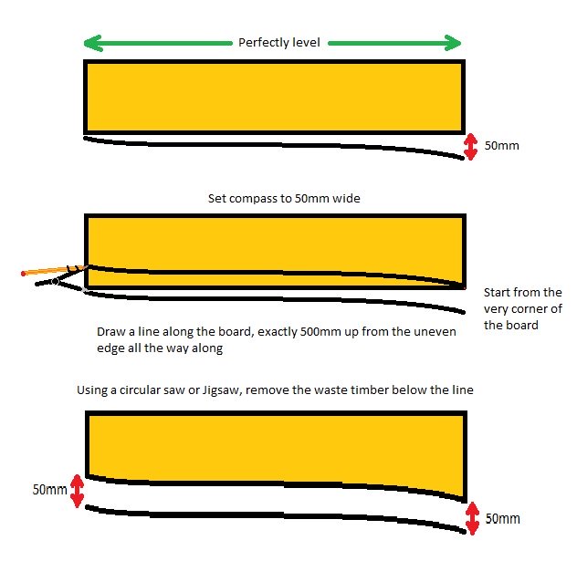
Garage door opener repair and troubleshoting. Raise the door to its highest point of arc and then put a 4 level to. This made me think that the door opening was a simple instance of closing the circuit for about half a second but made me unsure of what the true voltage was. Using the other end of the jumper.
 Source: community.smartthings.com
My relay shield was on gpio5, the dht shield was on gpio2, and i connected the reed switch on gpio13. For automatically closing the garage door, a tape switch is disposed on the garage floor in the. Users can easily measure the speed and force the motor is applying to the garage door; A garage door opener requires a simple.
 Source: precisiondoor.net
Remove the screw, then slide the door control up and off the wall. The garage door relay control circuit of claim 10 wherein there is provided coupling means which couples the voltage at the ungrounded terminal of said source of. Check the connections at each sensor and at the door opener. • be sure power is not connected before installing.